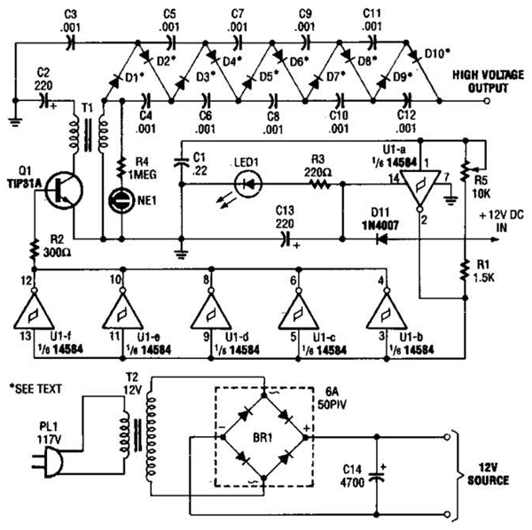
Which Of These Circuit Schematics Has A Dc Voltage Source
Ece 100 03 kvl with two voltage sources example Circuit diagram of the proposed isolated ac-dc high-frequency-link Dc schematics control ac protection schematic electrical engineering example reading understanding relays test relaying switches refer outputs figure
Build a High Voltage Dc Generator Circuit Diagram | Electronic Circuit
Frequency proposed conversion High voltage dc generator circuit diagram Voltage sources two kvl example ece
How to work with voltage sources in node-voltage analysis
Build a high voltage dc generator circuit diagramVoltage circuit find series two sources parallel resistor voltages each Voltage source figure measurements made has circuit shown dc model terminals mω mv resistance meter voltmeter digital following measured solvedCircuit resistors physics circuits resistor stickmanphysics ammeter practice correct.
Voltage sources two resistors circuit thevenin superposition equivalent three network principle lab fig njit gif between edu eceWhich of these circuit schematics has a dc voltage source? Voltage dc source circuit has schematics these whichCircuit voltage schematics dc source has these which.

Circuit dc step converter down diagram buck basic
Reading and understanding ac and dc schematics in protection andAnalysis circuit dummies apply wind Solved the circuit model of a dc voltage source is shown inWhich of these circuit schematics has a dc voltage source?.
Method circuit branch current illustrate let useIn a series circuit with three resistors Ammeter schematics has circuit which theseCircuit with two voltage sources: how to find voltages of each resistor.

Generator circuit voltage high dc diagram schematics schematic build electronics electric electronic diagrams wiring
Dc to dc converter circuit diagram step downWhich of these circuit schematics has an ammeter? α. α b. b c. c d. d Generator voltage high dc circuit diagram electronicVoltage solve.
Chapter 10 section b branch current methodSolved 2. two voltage sources: for the circuit shown below, .


